 Training Videos
Description
The LR750 is a compact inverter designed to integrate with elevator controllers. It monitors the mainline and, during a mainline failure, generates an AC voltage equivalent to the normal supply so the controller can perform rescue operation.
The LR750 has a 500 W power rating and is available in two classes. The LR750-2 provides a pure sine-wave output adjustable from 200 VAC to 240 VAC. The LR750-4 provides a pure sine-wave output adjustable from 400 VAC to 480 VAC.
The unit uses a UL Certified 24 V, 3.7 Ah battery pack. The battery is monitored continuously and charged by an intelligent 0.7 A, 28 V charging circuit so the rescue unit remains ready for emergency operation.

Specifications
Electrical
- Power output: 500 W
- Output waveform: Pure sine wave, 60 Hz
- LR750-2 output: Adjustable 200-240 VAC
- LR750-4 output: Adjustable 400-480 VAC
- Battery charging circuit: 0.7 A at 28 V
- Battery pack: 24 V, 3.7 Ah
Runtime and Protection
- Total runtime: 9 minutes at maximum power output
- Generation cycle: Stops after 3 minutes; press Button B to restart
- Battery test: Automatic every 24 hours with a known load
- Overcurrent protection: Stops operation on excessive battery current
- Overvoltage protection: Stops operation if output voltage exceeds the safety threshold
Mechanical
- Height: 7.3 in
- Width: 6 in
- Depth: 8.5 in
- Unit weight: 18 lb
- Shipping weight: 20 lb
Environment and Compliance
- Operating temperature: -10°C to 40°C
- Humidity: 95% non-condensing
- Altitude: Up to 1000 m
- Compliance: CSA Certified, CSA B44.1 / ASME 17.5
- Warranty: 3 years
Fuses and Enclosure
- A non-replaceable 30 A fuse is installed in series with the battery.
- The LR750-4 output fuse is 500 VAC, 1.6 A.
- The LR750-2 output fuse is 500 VAC, 3.15 A.
- The metal enclosure protects the internal circuits, battery pack, and electrical connections.
Theory of Operation
The LR750 operation is governed by four primary circuits: battery charging, battery test, main-line monitoring, and AC generation. These circuits are managed by the processor board, which monitors inputs, controls outputs, drives the OLED display, and reports status through relay contacts and CAN-BUS.
Battery Charging Circuit
The charging circuit uses a 36 V, 35 W supply powered from the external 120 VAC input at terminal J3. The charger produces a regulated 28 V DC output at 0.7 A. Battery voltage is monitored continuously. If the battery voltage exceeds the charge threshold, charging is disconnected to prevent overcharging. Charging is also disconnected while the unit is generating AC output.
Battery Test Circuit
The battery test circuit applies a known load and monitors the battery voltage response. If the battery can no longer hold adequate charge, the unit reports a fault condition so the elevator controller can respond. The automatic battery test runs every 24 hours. Button A can also be used to request a manual battery test.
Main-Line Monitoring Circuit
The main-line monitoring circuit watches the incoming supply. If the mainline drops below the valid threshold, the processor isolates the mainline from the output path and allows emergency generation when the safety input is active.
AC Generation Circuit
The LR750 generates a pure sine-wave AC output through its internal inverter and transformer. Output voltage is regulated automatically and can be adjusted with the ADJ potentiometer.
Processor Board Control
The processor monitors battery voltage, battery current, output voltage, mainline status, battery switch status, safety input, pushbuttons, and fault conditions. It controls charging, generation, battery testing, ready output, rescue output, OLED status, and CAN-BUS status transmission.
Connections and Controls
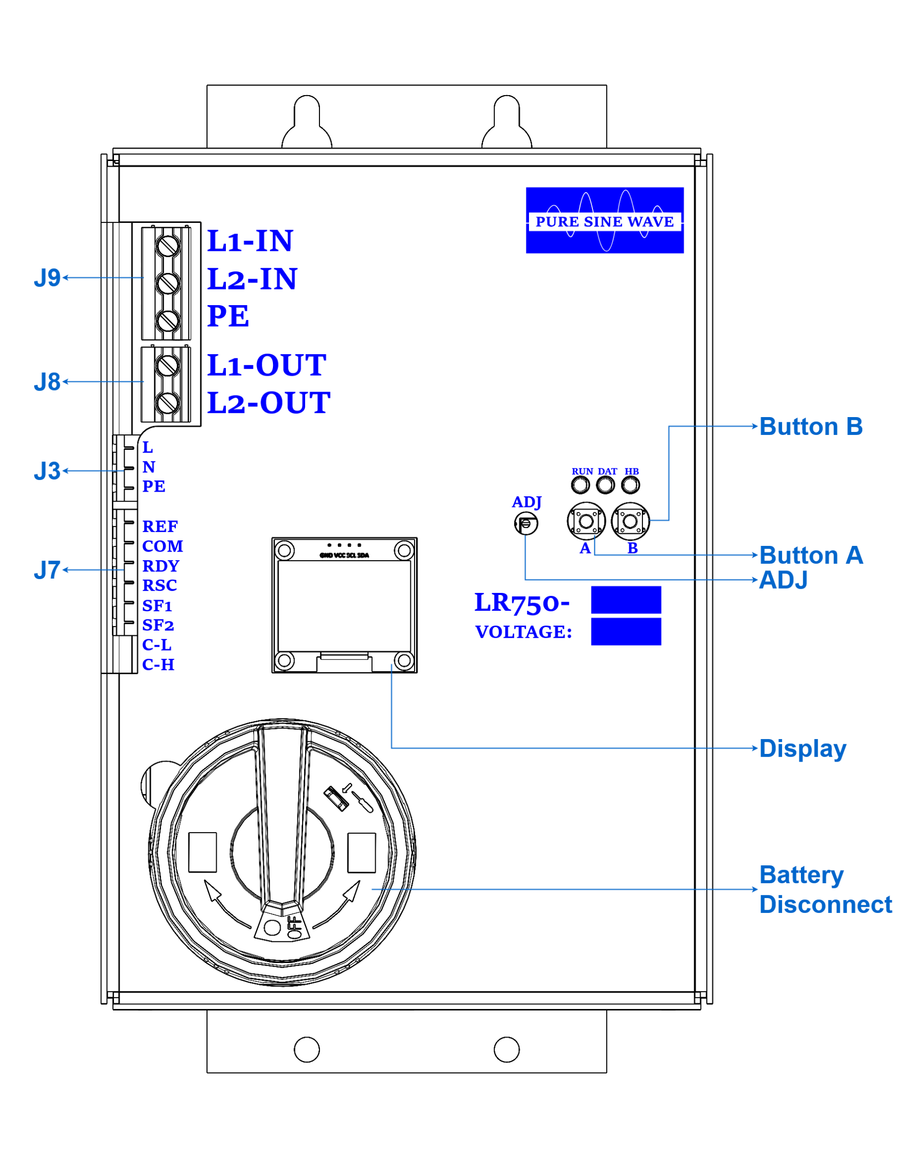
Terminal Details
| Terminal | Function |
|---|---|
| J9 L1-IN | Main-line input phase 1. |
| J9 L2-IN | Main-line input phase 2. |
| J9 PE | Earth ground. |
| J8 L1-OUT | Output phase 1 to the elevator controller. |
| J8 L2-OUT | Output phase 2 to the elevator controller. |
| J3 L | 120 VAC line input from the elevator controller for battery charging. |
| J3 N | 120 VAC neutral input. |
| J3 PE | Earth ground. |
| J7 REF | Connect to the controller REF terminal only when CAN-BUS communication is used. |
| J7 COM | Common for RDY and RSC dry relay contacts. |
| J7 RDY | Normally-open dry relay contact that closes only when the LR750 is ready to operate. |
| J7 RSC | Normally-open dry relay contact that closes only while the LR750 is actively generating AC output. |
| J7 SF1-SF2 | Safety contact input. Connect to the auxiliary contact of the main-line disconnect switch. |
| J7 C-L / C-H | CAN-L and CAN-H. A 120 Ω termination resistor is provided if needed. |
| ADJ | Output voltage adjustment potentiometer. |
| DISP | 1.3 in OLED status display. |
| SW | Lockable battery disconnect switch. |
| Button A | Left pushbutton. Starts a manual battery-health test. |
| Button B | Right pushbutton. Restarts the rescue unit after the generation timer expires. |
SWITCH OFF when this condition is detected.
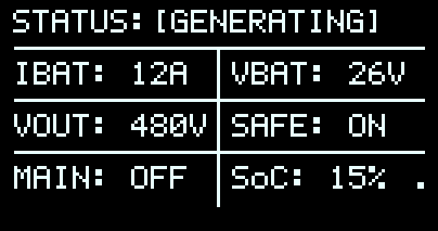
OLED Display
The OLED provides real-time operating status, battery measurements, output voltage, safety input status, mainline status, and battery state of charge.


Display Status Reference
Displayed Measurements
- IBAT: Battery current. Negative current indicates charging; positive current indicates discharge during generation or test.
- VBAT: Battery voltage. A fully charged battery displays approximately 27 V or above.
- VOUT: AC output voltage while generating. Adjust using the ADJ potentiometer.
- SAFE: ON means SF1-SF2 is connected. OFF means the safety input is open.
- MAIN: ON means main power is present and generation is inhibited. OFF means main power is unavailable and the unit can generate if safety is active.
- State of Charge (SOC) %: Displays the estimated battery state of charge as a percentage.
Screen Saver
The OLED enters screen saver mode after the configured inactivity period, normally 1 hour, to prolong display life. It exits screen saver mode when activity is detected.
Battery Open Detection
[BAT OPEN], leave the battery disconnect switch ON and give the LR750 time to recover. The condition normally clears automatically after the battery slowly recharges, typically within 30 minutes.
[BAT OPEN] can occur after the battery has been deeply discharged for a long time. In that condition, the battery pack may temporarily disconnect itself internally to manage recovery and charging. The LR750 battery disconnect switch may still be ON, but the battery itself is not yet accepting charge normally.
The LR750 uses this status to prevent a false fully-charged reading caused by charger voltage appearing at the battery input while the battery is internally disconnected. When the battery begins accepting charge again, the status clears automatically and normal ready operation can resume.
While [BAT OPEN] is active:
- The OLED displays
[BAT OPEN]. - The RDY contact opens and the LR750 reports not ready.
- The red fault indicator turns on.
- The CAN battery-full status bit is suppressed.
- Generation remains unavailable until the battery recovers.
- No operator reset is normally required; allow up to 30 minutes for slow recovery charging.
CAN-BUS Communication Protocol
The LR750 transmits status on CAN-BUS using a standard 11-bit CAN 2.0A data frame.
| Device | Dynavect LR750 Battery Rescue Device |
|---|---|
| Protocol | CAN-BUS 2.0A, 11-bit identifier |
| Baud rate | 125 kbps |
| Node ID | 0x750 |
| Frame type | Data frame |
| DLC | 8 bytes |
| Transmission rate | 500 ms, 2 Hz |
Payload
| Byte | Field | Description | Range | Resolution | Units |
|---|---|---|---|---|---|
| 0 | Status Flags | System status indicators | 0-255 | 1 bit/flag | - |
| 1 | Fault Flags | System fault indicators | 0-255 | 1 bit/flag | - |
| 2 | Battery SoC | State of charge | 0-100 | 1 | % |
| 3-4 | Battery Current | Unsigned battery current | 0-300 | 0.1 | A |
| 5-6 | Output Voltage | Output AC voltage | 0-500 | 1 | V |
| 7 | Reserved | Reserved for future use | 0-255 | 1 | - |
CAN Status and Fault Flags
Status Flags, Byte 0
| Bit | Flag | Description | Value |
|---|---|---|---|
| 0 | SAFE | Safety input status | 0 = Unsafe, 1 = Safe |
| 1 | MainLine | Main-line status | 0 = Off, 1 = On |
| 2 | Ready | RDY output status | 0 = Not Ready, 1 = Ready |
| 3 | Charging | Charging status | 0 = Not Charging, 1 = Charging |
| 4 | Bat Full | Battery full status. This bit is cleared when battery-open is active. | 0 = Not Full, 1 = Full |
| 5 | Generating | Generation status | 0 = Not Generating, 1 = Generating |
| 6 | Bat Test | Battery test status | 0 = Not Testing, 1 = Testing |
| 7 | Off SW | Battery switch status, inverted from the internal off flag | 0 = Switch Off, 1 = Switch On |
Fault Flags, Byte 1
| Bit | Flag | Description | Value |
|---|---|---|---|
| 0 | OV FLT | Output over-voltage fault | 0 = No Fault, 1 = Fault |
| 1 | OC FLT | Battery over-current fault | 0 = No Fault, 1 = Fault |
| 2-7 | Reserved | Reserved | 0 |
CAN Scaling and Examples
Scaling
| Field | Format | Example |
|---|---|---|
| Battery SoC | 0-100%, 1% resolution | 75% = 0x4B |
| Battery Current | 16-bit big endian, 0.1 A resolution, negative current clamped to 0 | 15.5 A = 0x009B |
| Output Voltage | 16-bit big endian, 1 V resolution | 240 V = 0x00F0 |
| Reserved | Current value 0x00 | Reserved for future expansion |
Example: Normal Operation Generating
CAN ID: 0x750
Data: [0xA5, 0x00, 0x50, 0x00, 0x09, 0x01, 0xB9, 0x00]
- Status byte
0xA5: safe, ready, generating, and switch-on status bits set. - Faults: none.
- SoC: 80%.
- Battery current: 0.9 A.
- Output voltage: 441 V.
Error Handling
| Missing frames | External receiver should treat device as offline after a 2500 ms timeout. |
|---|---|
| Invalid data | Receiver should check fields against valid ranges before processing. |
| Checksum | No payload checksum is implemented; CAN hardware error detection is used. |